
Is a load-bearing façade wall getting in the way of your plan to install a door, a glass screen or a window? As a delicate part of the structure, opening a load-bearing wall is a technical operation that requires the expertise of a building specialist.
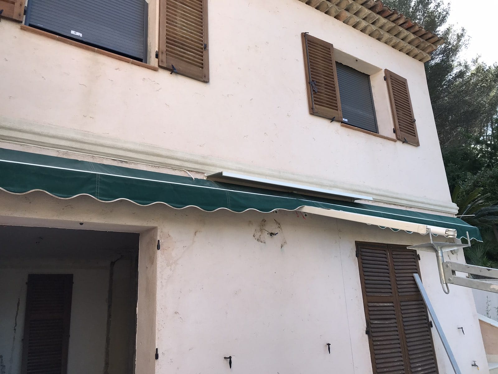
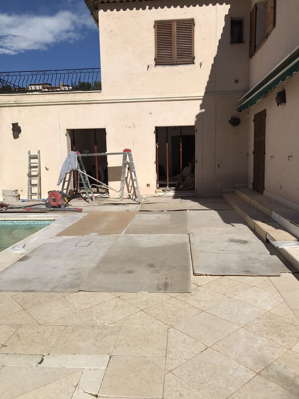
However, when enlarging glazed openings, it may be necessary to break through a load-bearing façade wall. This was the case with the renovation of a villa in Saint-Jean Cap Ferrat. The owner wanted to let more light into the rooms so that they would feel brighter.
Given the scale of the operation, it was clear that a structural engineer was needed for the project study. His analysis defined the right method for enlarging glazed openings while cutting into the load-bearing façade wall.
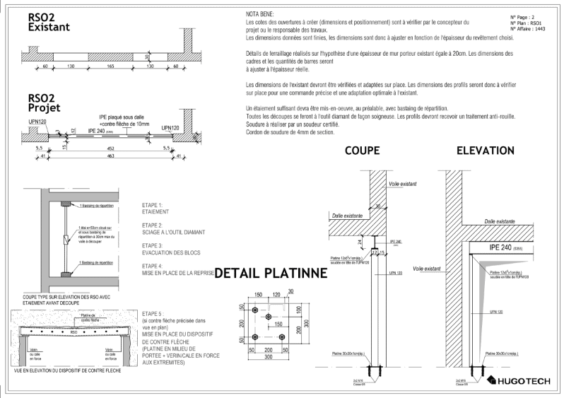
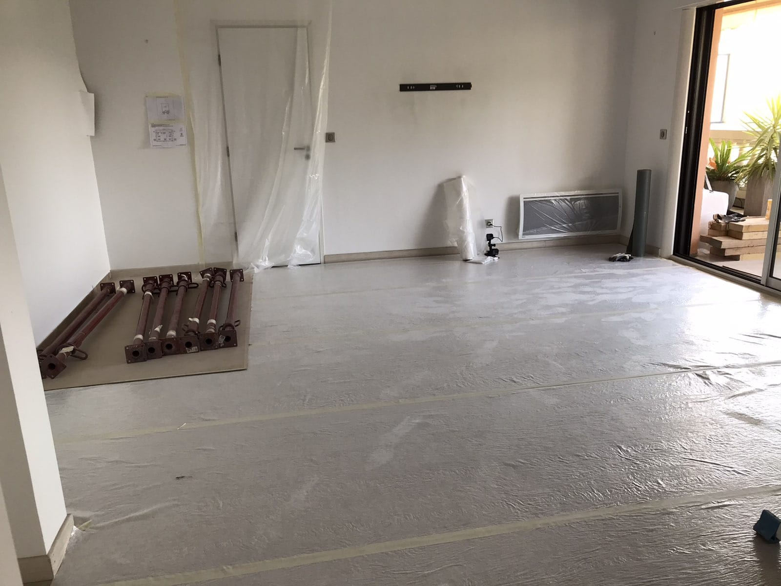
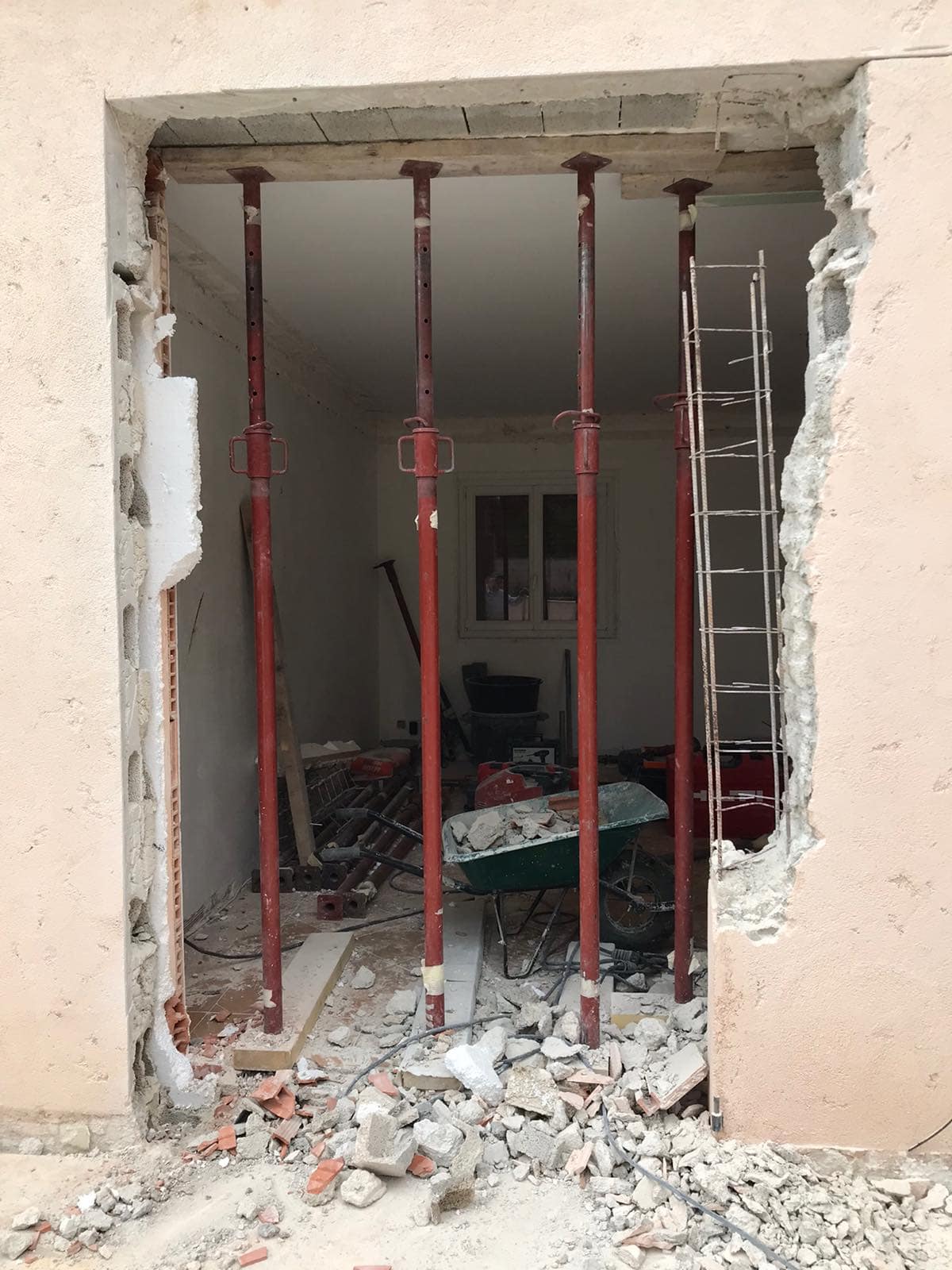
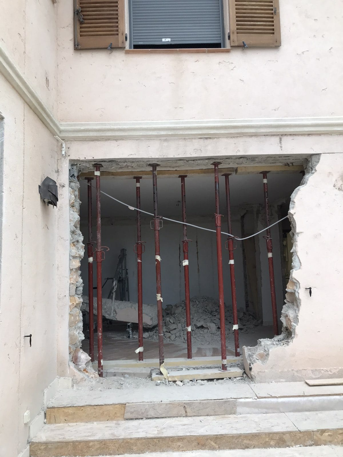
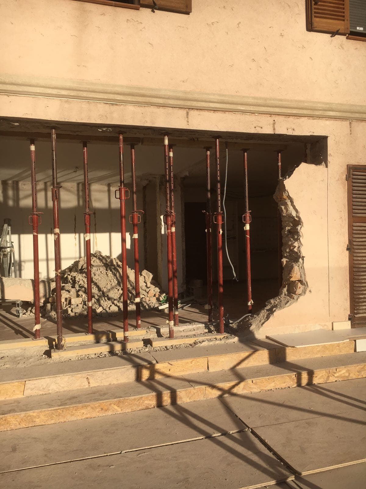
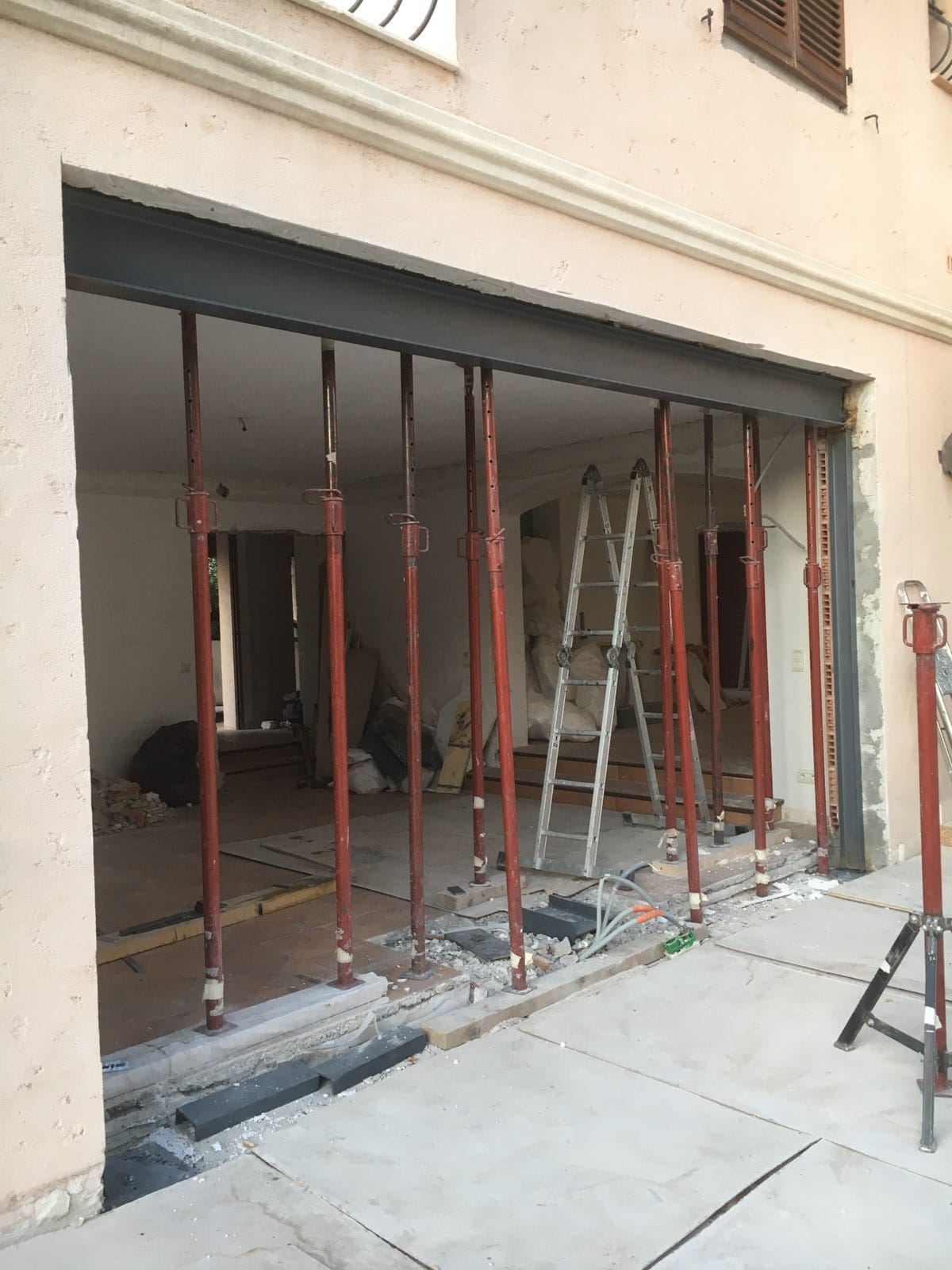
As usual, we start the job by preparing the work area. Protective sheeting and hardboard panels are put in place to protect the floor and walls from debris. Since clearing the load-bearing wall can destabilise the upper level of the structure, it had to be supported. So, before taking down the load-bearing wall, we took care to fix timber planks to carry the upper floor.
Each plank is held by a pair of props. Above the lintel, close to the ceiling, we cut holes in the false ceiling to reach the existing structure, at intervals of 50 to 60 cm, so the planks can be driven in deep. Note that to offset the weight of the structure and keep it balanced, the planks must run parallel to the wall.
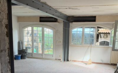
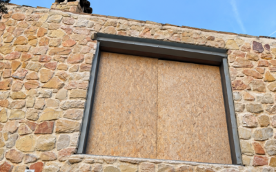
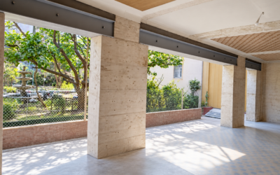
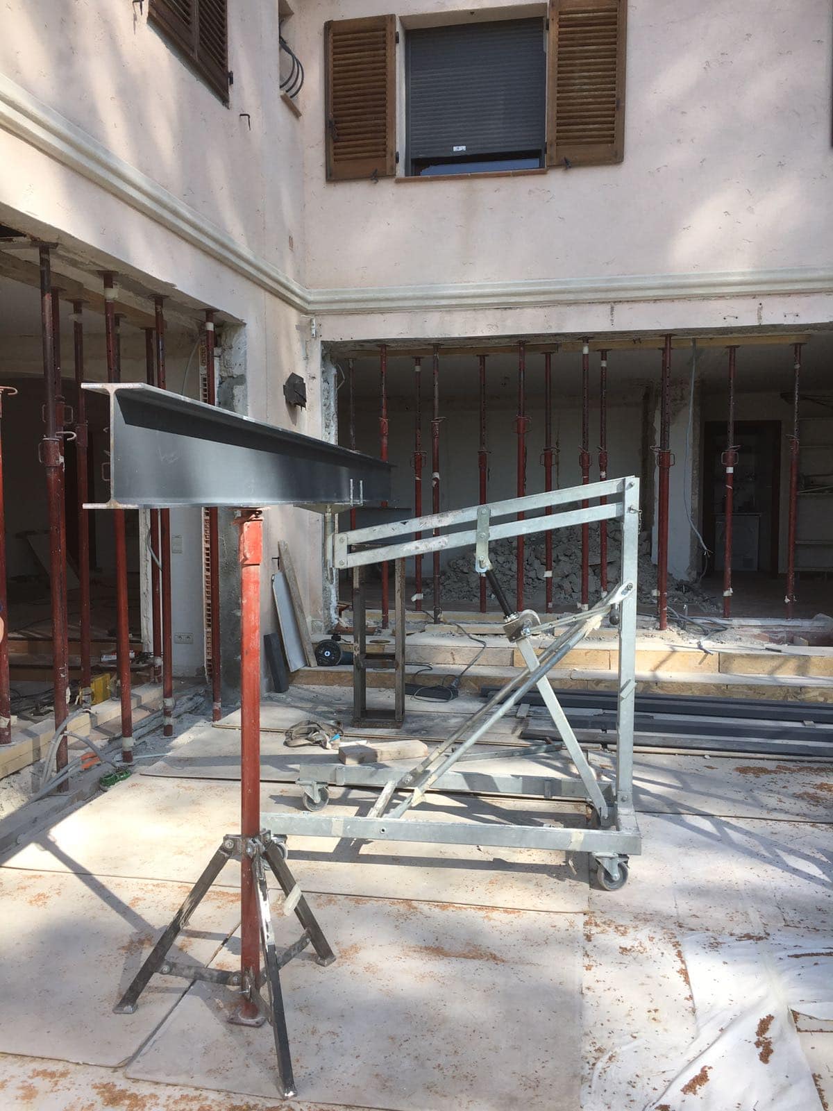
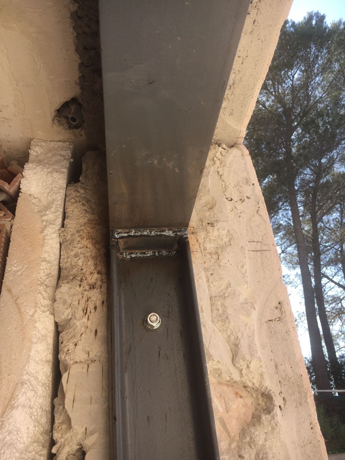
To create an opening more than 2.5 cm wide, we used the portal frame technique. An effective way to strengthen the future installation, the portal frame guarantees the stability of the side section between the wall and the opening. To do this, two vertical columns form the jambs, and a horizontal beam is fixed above them by bolting and welding. The columns, or vertical sections, are anchored to the floor by footings able to carry the full load.
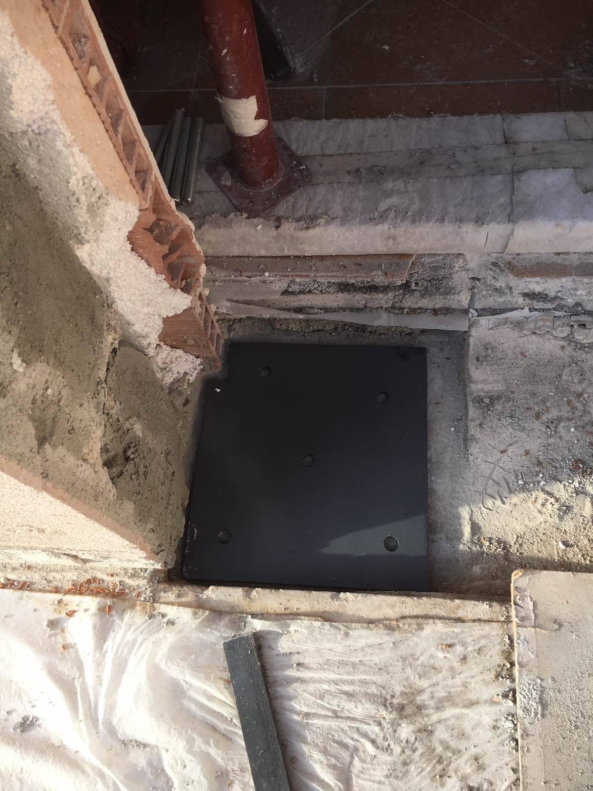
For the steel reinforcement, we chose two UPN120 columns and an IPE240 beam. The columns are fixed to the walls with chemical anchors and to the floor with lag screws. The beam is then placed on top of the two columns.
This involves fixing the IPE240 beam by wedging and bedding in non-shrink mortar. We also wedged all the existing beams along a perpendicular RC plane. To strengthen the steel structure, we fixed base plates to both ends of the columns with a continuous weld.
Once this was done, we finished the job with an anti-rust treatment of all the steelwork. Before leaving the site, the waste materials are taken to the recycling centre and the floor is cleaned from top to bottom.